
KMF Split Thin-Section Bearings Application in a Tunable Permanent-Magnet System for Particle Accelerators
TECHNICAL APPLICATION REPORT / SCIENTIFIC EQUIPMENT
German KMF Split Thin-Section Bearings
Application in a Tunable Permanent-Magnet System for Particle Accelerators KMF Split Thin-Section Bearings
Applicati
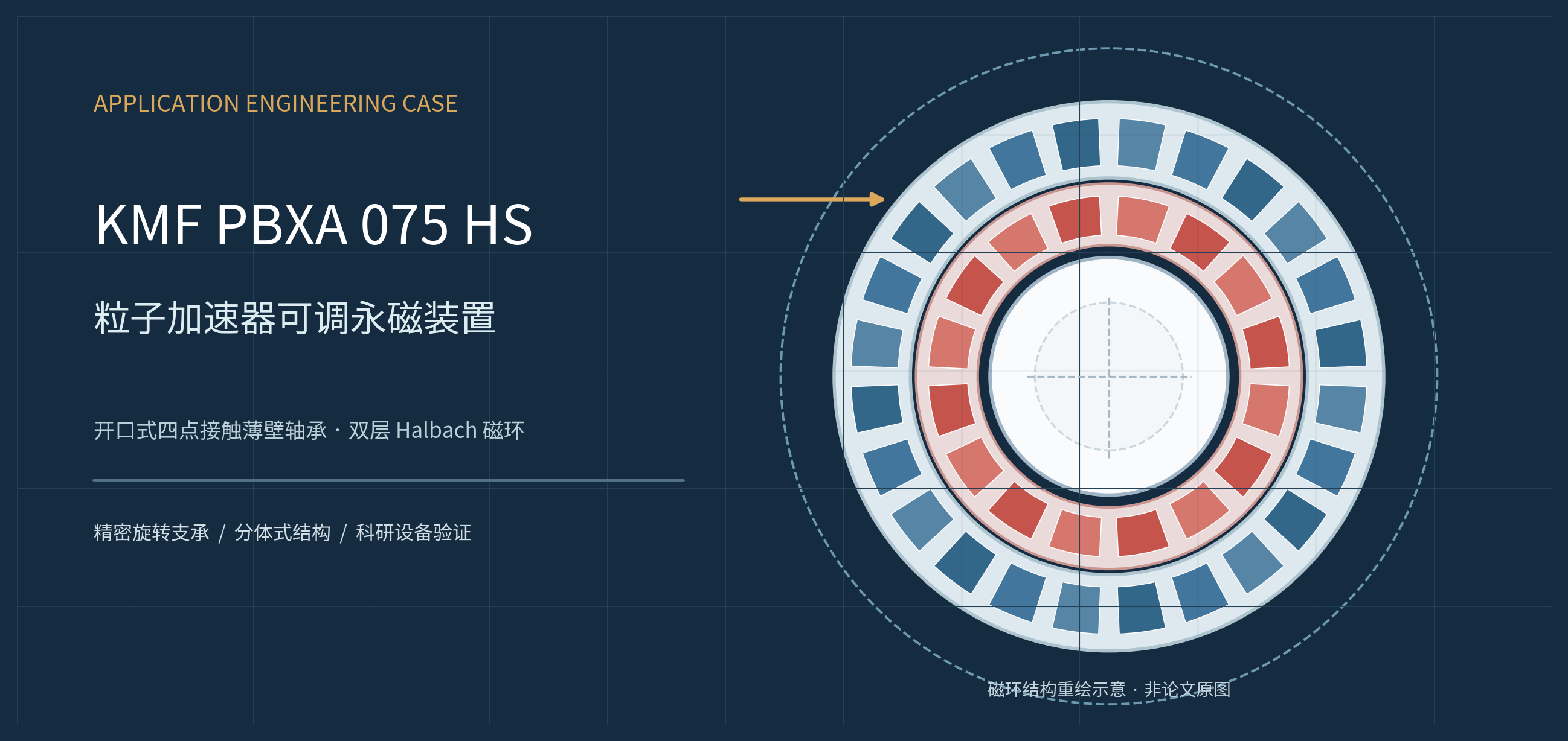
Original engineering concept illustration: dual Halbach magnet rings and central beam passage. Proportions and component appearance do not represent the actual engineering drawings in the paper.
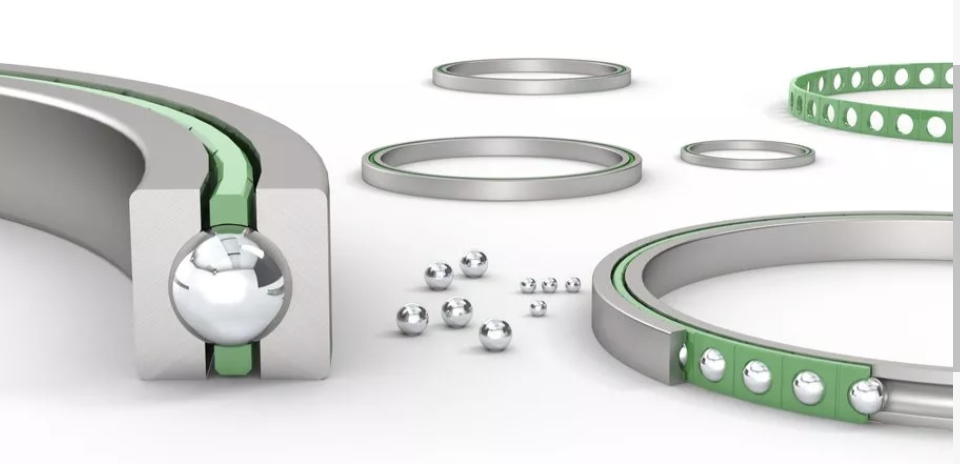
CASE PROFILE
Application Equipment | Bearing Model | Publicly Available Evidence |
Openable, tunable permanent-magnet quadrupole | KMF PBXA 075 HS | 2025 APS peer-reviewed paper |
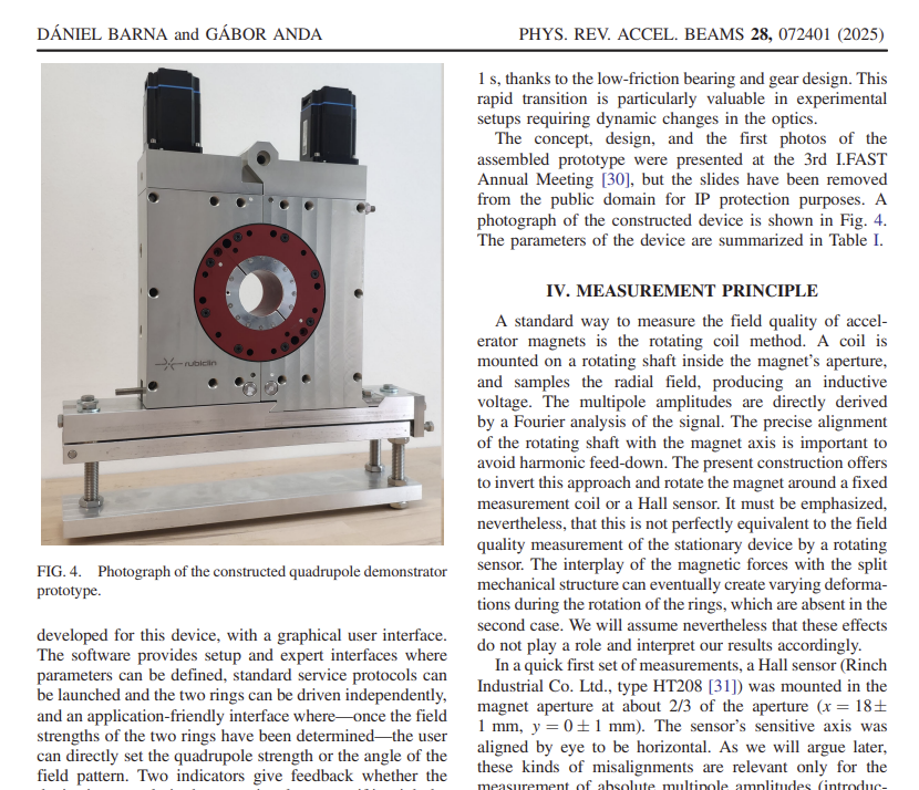
Source study: Dániel Barna and Gábor Anda; HUN-REN research institutes; prototype designed and manufactured by Rubiclin Ltd.
Compiled by: Hangzhou Rongyi Technology Co., Ltd. | October 2026 | Technical literature review · Not an official joint case study with the manufacturer
01 / PROJECT OVERVIEW
Research Summary and Strength of Evidence
In 2025, a Hungarian research team presented a quadrupole magnet prototype that can be opened from the side and comprises two independently rotating concentric Halbach permanent-magnet rings. In the “Prototype Design” section, the paper explicitly identifies KMF PBXA 075 HS slim split bearings for the external support and independent rotation of the rings. The prototype was designed and manufactured by Rubiclin Ltd., followed by drive-system and magnetic-field measurements. [1]
Original source | Photograph of the actual prototype: APS paper, Fig. 4 (PDF p. 6)
Core Verifiable Finding The public evidence identifies the bearing brand and model in a peer-reviewed paper and describes its use in a manufactured prototype. It confirms that a KMF product was incorporated into the mechanical design of a scientific instrument. It does not establish that CERN directly purchased KMF bearings, nor are the magnet’s measured magnetic properties standalone bearing performance results. |
Four Key Device Specifications
Device Characteristic | Value Reported in the Paper | Type of Evidence |
Beam Aperture / Overall Length | 54 mm / 80 mm | Prototype geometry |
Permanent-Magnet Configuration | Inner ring: 16; outer ring: 24 | Prototype configuration |
Central Gradient Adjustment Range | 7.75–17.75 T/m | Measured |
Min.–Max. Field Switching Time | Approx. 1 second | System-level demonstration |
Why Does This Study Matter to the Bearing Industry?
This is not merely a promotional claim that “bearings can be used in magnets.” Rather, the published scientific paper provides a connected account of the bearing grooves, split construction, worm drives, assembly sequence, independent ring rotation and experimental results. The role of the bearings can therefore be traced to the mechanical design of a real device. [1]
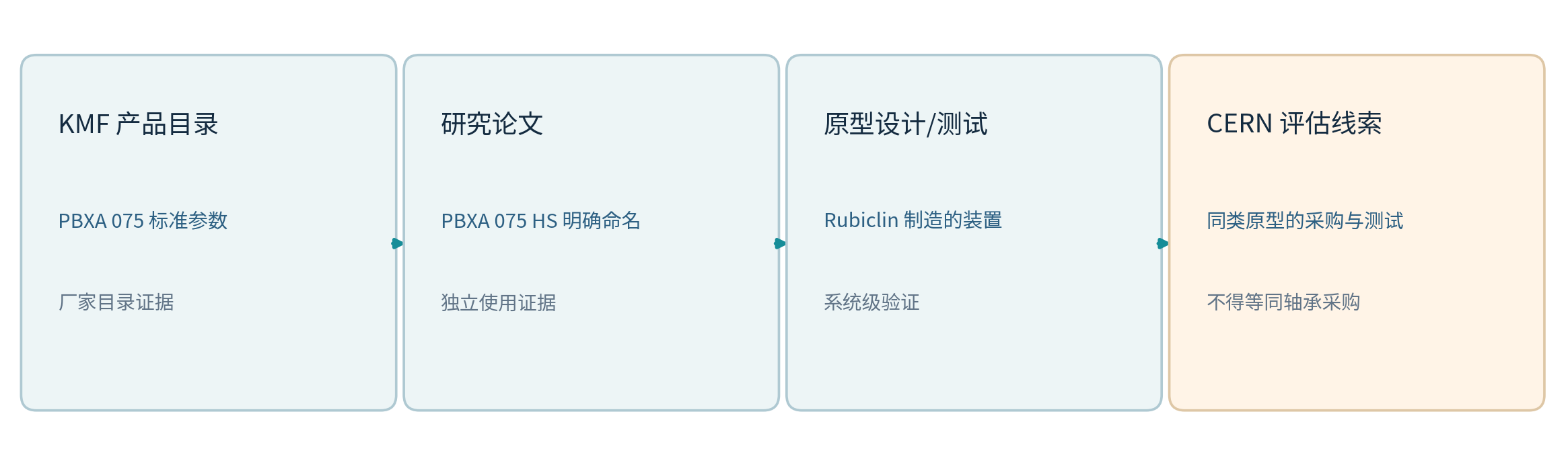
Fig. 1 Evidence chain and limits of the CERN association (originally redrawn based on [1]–[3]).
Application Background: Why Are Tunable Permanent Magnets Needed?
Particle accelerators use magnetic fields to control the trajectories and focusing of charged particles. Conventional electromagnets provide convenient field adjustment but require excitation power and associated thermal management. Permanent magnets can maintain a steady field without continuous excitation current, although tunability is more difficult. This study seeks to combine the benefits of both approaches: permanently magnetized materials generate the field, while mechanical rotation varies the magnitude and direction of the resultant field. [1]
Quadrupole magnets provide transverse focusing of particle beams. In this two-ring arrangement, the inner and outer rings each generate a quadrupole component. Changing their relative angular positions varies the resulting focusing strength within a certain range. Coordinated rotation changes the orientation of the field pattern and, where required, permits polarity reversal.
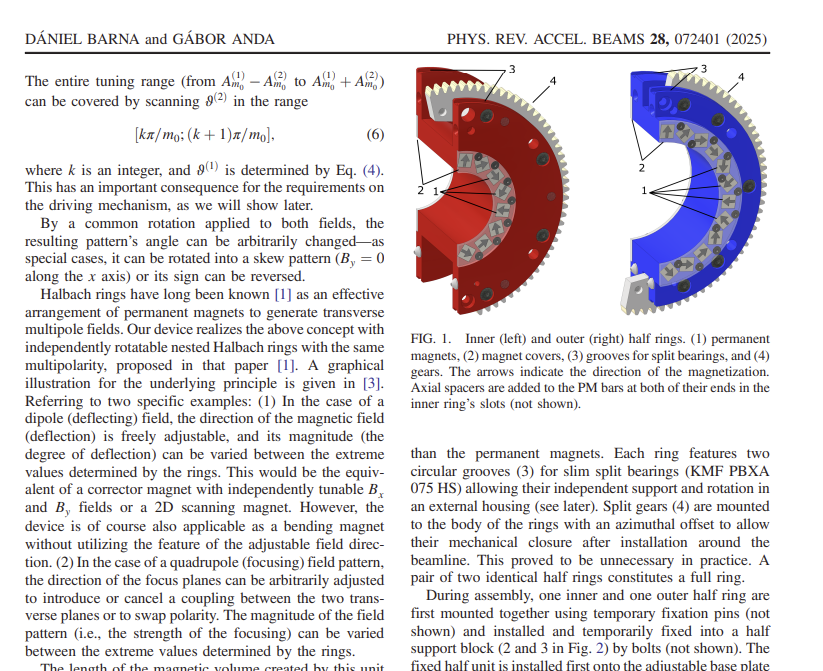
Original source | APS paper, Fig. 1: actual inner- and outer-ring designs (PDF p. 4)
Why Does This Affect Bearing Selection?
Conventional one-piece closed-ring bearings are not inherently suited to a mechanism that must close around an existing beam pipe. This project requires two concentric magnet rings to rotate independently, the complete assembly to open and close, and the support geometry to return precisely to position. The bearings are therefore not only load-carrying elements, but also mechanical interfaces that must be considered together with the installation arrangement, drive train and repeatable-positioning strategy.
Prototype Assembly: Where Exactly Are the Bearings Installed?
Figure 1 of the paper shows that both the inner and outer magnet rings are made from two semicircular halves. The magnets sit in rectangular pockets in the aluminum rings and are secured with cover plates. The authors explicitly state that two circular bearing grooves are machined into each ring to accommodate KMF PBXA 075 HS slim split bearings, thereby providing separate support and rotation of the two rings within the external housing. [1, p. 4]
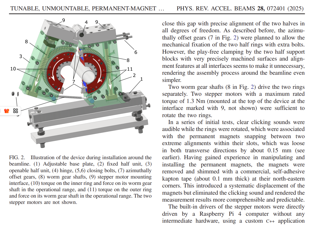
Fig. 3 Redrawn functional layout of the magnet front face. For explanatory purposes only; bearing interfaces are not shown to actual dimensions.
Original source | APS paper, Figs. 1 and 2: actual structural and assembly drawings (PDF pp. 4–5)
Key Component | Function |
Inner Halbach Ring | Generates one quadrupole permanent-magnet field and rotates independently about the central axis |
Outer Halbach Ring | Generates a second quadrupole field; works with the inner ring to tune the field |
KMF Split-Bearing Grooves | Provide support interfaces inside the outer housing, allowing both rings to rotate independently |
Central Aperture | Allows passage of the existing beam pipe; not the bearing bore diameter |
Worms / Gears / Stepper Motors | Control relative ring positions and coordinated movement |
Engineering Role of the Bearings: Converting Field Control into Repeatable Mechanical Rotation
01 · Providing Independent Rotational Support
Although concentric, the two magnet rings must move at different angular speeds and to different target angles. The bearings provide rolling support between each ring and the stationary housing, helping the housing and transmission elements constrain unwanted displacement. The paper directly describes the relationship between “two bearing grooves,” “external support” and “independent rotation.” [1]
02 · Supporting a Split, Openable Installation
The paper shows that the magnet rings and external frame are divided into a stationary half and an openable half, allowing the device to close around a beam pipe already in place. The KMF product is identified as a “Slim Split Bearing,” indicating that split-bearing construction forms part of the mechanical design. However, the paper does not disclose detailed assembly tolerances at the bearing joints or the supplied quantity; the exact bearing installation procedure should not be inferred.
03 · Enabling Low-Resistance Rotation and Fast System Response
The paper notes that, with a low-friction bearing and gear design, the apparatus can switch from the minimum- to the maximum-field configuration in approximately one second. Importantly, this figure describes the response of the complete drive and mechanical system; it is not a standalone speed or friction-torque test of the KMF bearing. [1, p. 6]
04 · Supporting Coaxiality and Positional Repeatability
Field adjustment depends on the angular and spatial relationships between the inner and outer rings. Accordingly, the assembly must address support rigidity, coaxiality, bearing clearance and transmission backlash together. The paper does not report the axial preload, measured radial runout or stiffness of the KMF bearings in this application; this interpretation is therefore limited to mechanical functions and interface requirements.
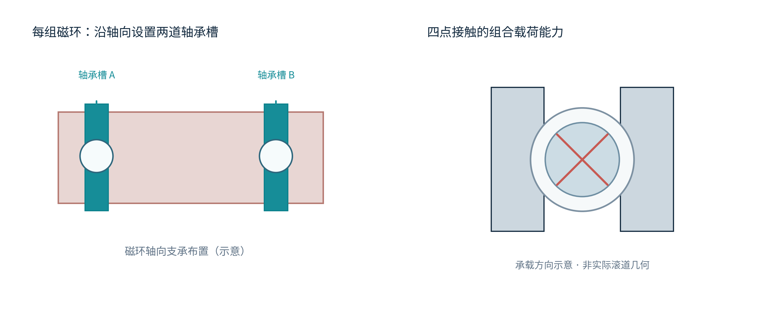
Fig. 4 Schematic of two axially separated bearing grooves and four-point-contact load paths; the right-hand drawing is not an actual KMF raceway section.
Field Assembly Concept for the Split Magnet
The original paper describes mounting the stationary half-unit on an adjustable base, positioning the upper openable half-unit, and closing it using a hinge and threaded closing mechanism. Once closed, accurately machined mating surfaces of the support blocks provide precise alignment. Before the closing mechanism is tightened, magnetic forces and gravity leave a gap of approximately 2 cm at the bottom of the upper half; mechanical closure is then completed. [1, pp. 4–5]

Fig. 5 Assembly-explanation flow reorganized from the prototype design described in the paper; not an actual construction work instruction.
Original source | APS paper, Fig. 2: actual openable prototype and support assembly (PDF p. 5)
Misinterpretation to Avoid An openable device does not imply that bearing accuracy need not be rechecked after disassembly and reassembly. Fits, tolerances, clearance, preload and joint treatment must follow the manufacturer’s approved drawings. |
KMF PBXA 075: Standard Catalog Specifications
The official KMF PBXA catalog specifies standard-series dimensions, basic axial and radial load ratings, mass and limiting speed with grease lubrication. The published catalog values for PBXA 075 are listed below. [2]
Catalog Parameter | PBXA 075 Standard Value | Interpretation / Limitation |
Nominal Bore d | 190.50 mm | Bearing bore; not the particle-beam aperture |
Nominal Outside Diameter D | 203.20 mm | Standard catalog dimension |
Nominal Cross Section | 6.35 × 6.35 mm | Based on diametral difference and official assembly drawing |
Basic Axial Dynamic Load Rating Ca | 6.10 kN | Apply the manufacturer’s catalog definition |
Basic Axial Static Load Rating C0a | 40.5 kN | Not directly equal to the allowable equipment load |
Basic Radial Dynamic Load Rating Cr | 5.50 kN | Operating conditions and service-life calculation required |
Basic Radial Static Load Rating C0r | 16.3 kN | Assess against the applicable static-load criteria |
Catalog Mass | Approx. 0.15 kg | Standard-model value |
Grease-Lubricated Limiting Speed | 800 r/min | Not the actual rotation speed of this magnet |
The “HS” Suffix Has Not Been Verified The full model designation in the paper is “PBXA 075 HS.” The table above lists only publicly available standard PBXA 075 catalog values. The open sources do not explain the technical meaning of the “HS” suffix or establish that this research configuration matches the standard catalog in material, internal clearance, sealing or preload. Confirm the exact version with KMF before procurement or interchange. |
Bearing Design Verification Checklist for Similar Equipment
Mounting geometry: dimensional tolerances, roundness, coaxiality and assembly feasibility for the bearing grooves and stationary housing.
Loads: ring self-weight, torque due to magnetic coupling, worm-gear reaction forces and localized stresses during opening and closing.
Support performance: axial and radial clearance, preload, tilting stiffness, frictional resistance and smoothness of rotation.
Operating environment: temperature, conditions near the vacuum system, stray magnetic fields, lubricant stability and contamination control.
Maintenance verification: alignment recovery after disassembly, interface fastening, transmission backlash and actual bearing service life.
Motion Control: How Do the Bearings Work with the Stepper Motors and Worm Drives?
The paper uses two worm shafts to drive the magnet rings separately. Two stepper motors, each with a maximum rated torque of 1.3 N·m, were sufficient to actuate the prototype. The motor drivers interface with a Raspberry Pi 4 and are controlled through a C++ graphical interface developed by the researchers. The software allows each ring to rotate independently or permits direct setting of the target quadrupole strength and field-pattern orientation. [1]
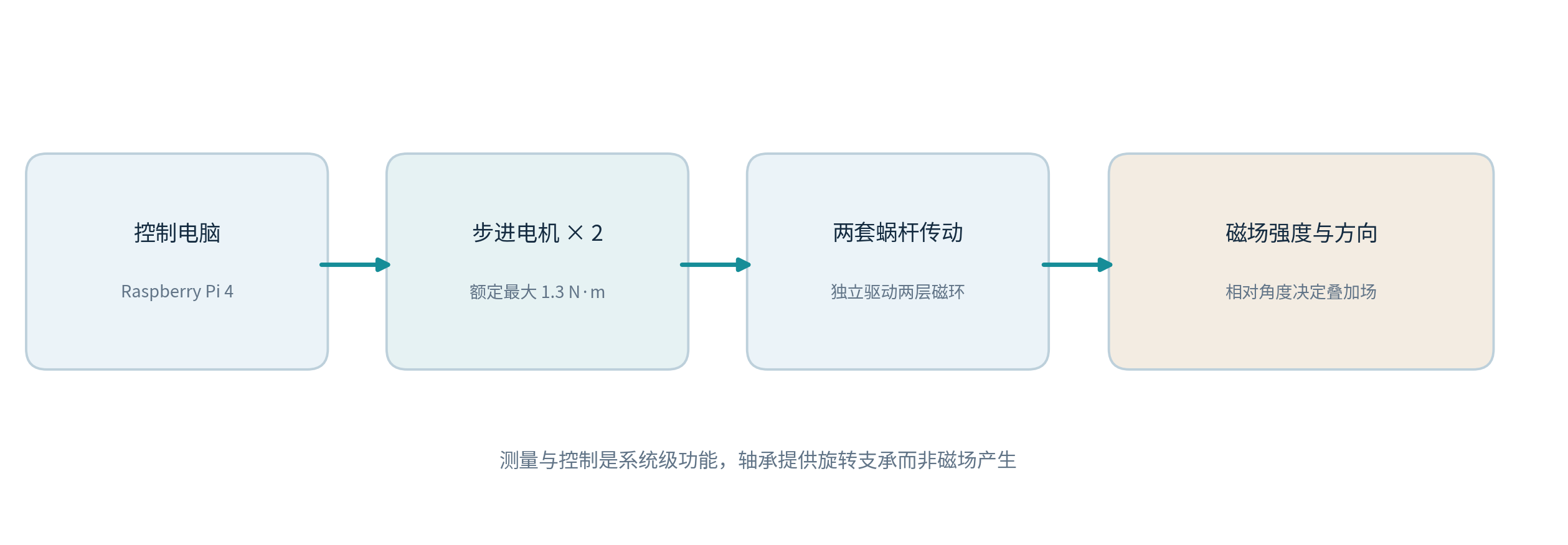
Fig. 6 Simplified prototype drive-control chain, based on the device description in the paper.
Original source | APS paper, Fig. 3: actual motion-control software interface (PDF p. 5)
Why Must Mechanical Backlash Be Considered?
Early in the study, the magnet rings made audible “clicking” sounds as they rotated. Further inspection found that the magnet pockets were slightly larger than the magnets, leaving approximately 0.15 mm of transverse play. The team shimmed the magnets using approximately 0.1 mm-thick Kapton tape, eliminating noticeable movement and clicking and making the measurements easier to interpret. [1]
This issue occurred at the magnet-to-ring pocket interface; the paper does not identify it as a quality defect in the KMF bearing. The study also discusses backlash in the drive system and the selection of operating ranges. Suitable drive strategies can reduce the effect of backlash on the repeatability of field strength.
Measured Results: What Did the Complete Magnet System Achieve?
The paper compares experimental results from the magnet prototype with three-dimensional COMSOL simulations. The principal measurements used a stationary Hall sensor at approximately two-thirds of the aperture radius. The whole magnet was rotated, and Fourier analysis of the data was used to extract the different multipole field components. [1]
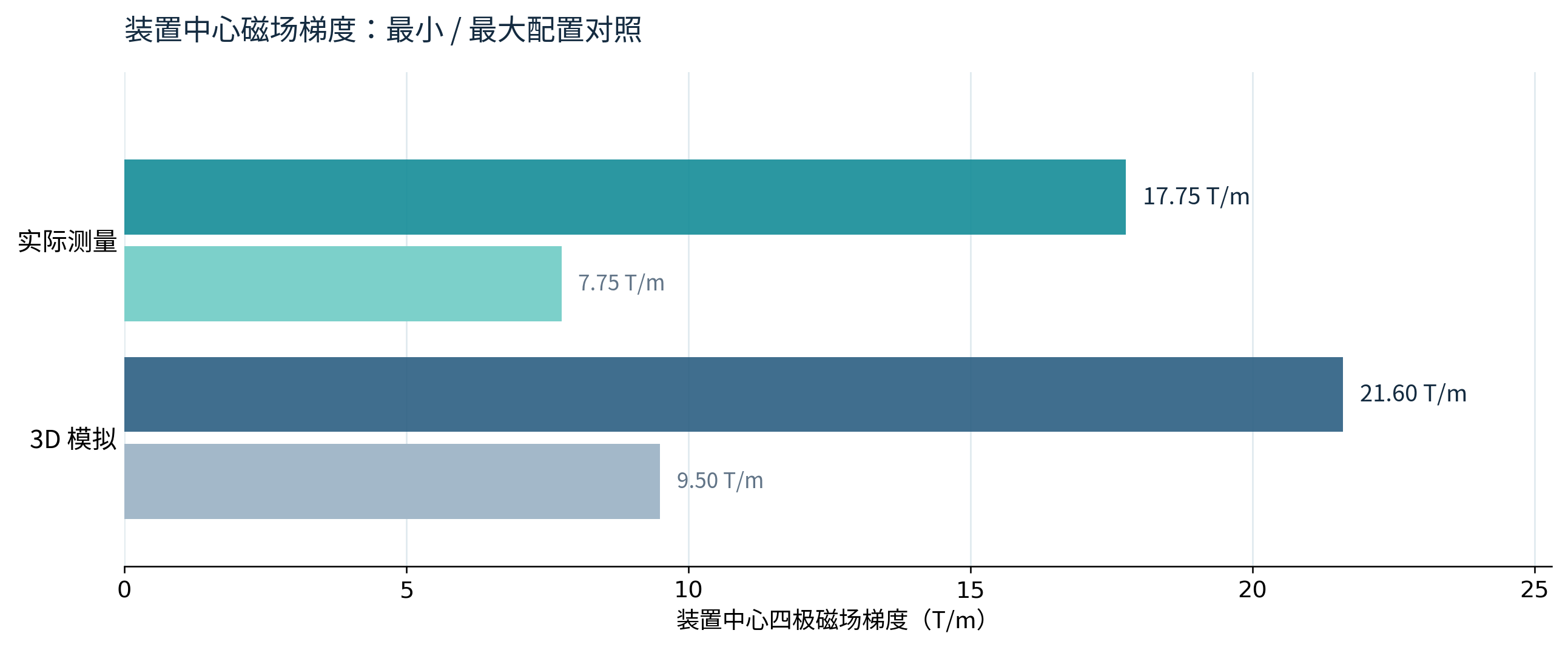
Fig. 7 Minimum and maximum central quadrupole gradients. Values taken directly from Table II of the original paper, without interpolated or invented intermediate measurements.
Original source | APS paper, Fig. 4: prototype photograph and parameter table (PDF p. 6)
Performance Metric | Actual Measurement | 3D Simulation |
Central Quadrupole Field Gradient Range | 7.75–17.75 T/m | 9.5–21.6 T/m |
Quadrupole Component at Maximum Setting | 319.6 mT | 389 mT |
Quadrupole Component at Minimum Setting | 139.6 mT | 172 mT |
Integrated Gradient Range | 0.36–1.01 T (estimated by scaling simulations to measurements) | Not independently measured directly |
These data demonstrate that the prototype underwent physical testing, but they describe the magnetic performance of the complete device—not a claim that “the bearing increased the field gradient to 17.75 T/m.” The field gradient is primarily determined by permanent-magnet material, ring geometry and relative angular positions. The bearing supports mechanical implementation and stable motion.
Magnetic Field Quality and Error Analysis
The study reports that undesired multipole components are generally at least two orders of magnitude below the dominant quadrupole component. Significant differences remained between measurement and idealized simulation. The authors consider variations in magnet remanence, assembly and positioning errors to be important factors. Early movement of magnets within their pockets also complicated interpretation of results. These findings do not establish that KMF bearings caused the magnetic-field errors. [1]
The first prototype was evaluated using relatively inexpensive N52 NdFeB magnets without tightly screened tolerances. The authors also note that the temperature and radiation resistance of this magnet grade is unsuitable for direct use in certain radiation environments; further applications would require reassessing the magnet grade along with mechanical and thermal requirements.
Engineering Implications: What Other Advanced Equipment Might Benefit?
The device demonstrates not a need confined to a single industry, but a combination of design constraints: compact coaxial rotation + openable housing + independent motion control + repeatable precision positioning. Similar challenges can occur in scientific instruments, optical scanning mechanisms, custom robotic rotary platforms and certain precision experimental assemblies.
Equipment requiring rotary components to be installed around existing pipes, axes or large annular workpieces.
Concentric rotating mechanisms with room for multiple axial support points but limited radial installation space.
Precision assemblies subject to radial and axial loads as well as overturning moments, requiring a tailored support arrangement.
Systems performing frequent small-angle movements or controlled large-angle rotations that are sensitive to backlash and friction variation.
These are potential engineering application areas inferred from the structure, not evidence of KMF purchase orders in those industries. Actual bearing selection still requires complete verification of loads, fits, operating environment and service life.
CERN Association: How Should the Project Be Described?
According to a product page published by the prototype manufacturer, Rubiclin, CERN purchased and tested a prototype based on this technology for evaluation. [3] However, that page does not specify the bearing model or procurement details of the unit concerned. It therefore cannot support a statement that “CERN purchased KMF PBXA 075 HS bearings.”
Recommended Public Wording A 2025 research paper published in Physical Review Accelerators and Beams explicitly documents the use of KMF PBXA 075 HS slim split bearings as rotary supports in a tunable permanent-magnet quadrupole prototype manufactured by Rubiclin. The manufacturer separately reports that CERN purchased and tested a prototype of this technology for evaluation; however, no direct evidence has been identified that CERN purchased KMF bearings. |
Evidence Levels for External Publication
Supported by Evidence | Not Established by Evidence |
The paper identifies KMF PBXA 075 HS | KMF is a bearing supplier to CERN |
Rubiclin designed and manufactured the prototype | The research institute placed a direct order with KMF |
The device has bearing-supported, independently rotating magnet rings | The bearing itself was tested at 17.75 T/m |
The prototype underwent gradient and switching tests | The HS suffix necessarily denotes a specific material or preload class |
References and Original-Source Verification
[1] Dániel Barna, Gábor Anda. Tunable, unmountable, permanent-magnet-based accelerator magnet. Physical Review Accelerators and Beams 28, 072401 (2025). DOI: 10.1103/m58n-mjcb. https://journals.aps.org/prab/pdf/10.1103/m58n-mjcb
[2] KMF Bearings. SLIM-SPLIT-BEARING — four point contact bearing, PBXA series,
https://www.rongyikeji.net/h-nd-1157.html
[3] Rubiclin Ltd. Tunable permanent magnet based accelerator magnets. https://rubiclin.com/index.php/products/tunable-permanent-magnet-based-accelerator-magnets/
Images, Copyright and Source Notes All mechanical, conceptual, data and flow diagrams in this report are original explanatory redrawings based on published papers and manufacturer catalogs, not source figures or manufacturer photos. For technical analysis only; models and supply terms are subject to current manufacturer documentation. No official commercial endorsement by KMF, the research institutes, Rubiclin or CERN is implied. Hangzhou Rongyi Technology Co., Ltd. · www.rongyikeji.net |
Citation and reuse notes: The APS article is open access under CC BY 4.0. Reuse of original figures should retain the authors, paper title, journal, volume, year and DOI (10.1103/m58n-mjcb). The KMF catalog and Rubiclin materials are subject to the latest versions published by their respective rights holders.